Here is a simple but very effective way of eliminating that nasty trigger
over-travel. This great little tip was given me by David Lake of
Composite Gunsmithing
and Custom CARBON FIBER and KEVLAR stocks and pistol grips;
http://compositeguns.com
. I have found David
to be both knowledgable and eager to help with advise based on experience.
Although this can be done to any trigger that has no over-travel adjustment,
below is detailed the procedure used for making an adjustable over-travel on a
Ruger
10/22 rifle.
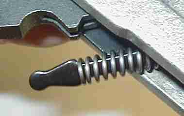
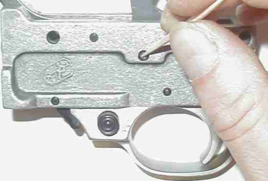
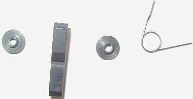
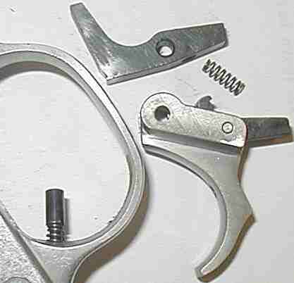
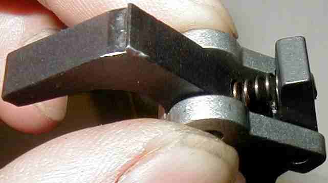
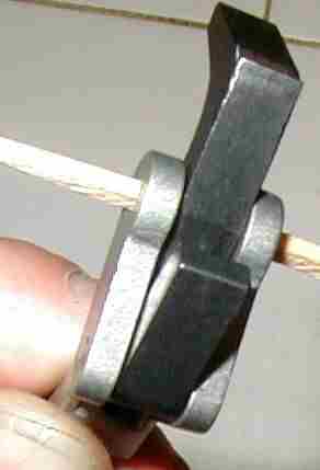
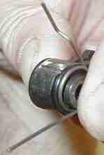
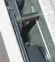
The trigger was
removed
from its assembly and a hole was simply drilled and
tapped through the trigger so that a 6 X 32 set screw could be screwed through
it. The hole was drilled so that the screw resides just above the trigger
spring and at a like angle as the spring. This position places the screw as
far out of sight as possible and drives the screw directly onto the inside face
of trigger guard when the trigger is depressed.
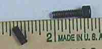
The set screw was fashioned by cutting the head off a 1/2 inch 6 X 32 hex screw
and cutting a screw driver slot in its place. It was then shortened so that it
would not protrude from the trigger face when adjusted. The screw was then
re-blued using a good cold blue solution.
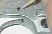
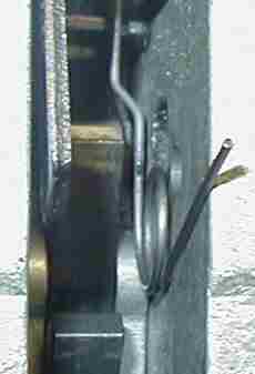
After field testing to determine the optimum adjustment (zero over-travel
without interfering with trigger pull) the screw will be locked in place with a
thread lock; a drop of super glue, finger nail polish or the like on the back
side of trigger.
Left - The hammer strut and spring assembly (B18, B44, B45) is pulled out after
un-cocking the hammer.
Center - The hammer pivot pin (B19) is pushed out.
Right - The hammer (B17), hammer bushings
2
(B43), and bolt lock spring (B42) are removed.
Left - The trigger pivot pin (B21) is pushed out.
Right - The trigger/disconnector/disconnector pivot pin assembly (B20, B25,
KE-28), sear (B23) and sear spring (B24) are removed by pushing trigger through
the top of trigger guard (B2).
Left - The disconnector (B25) is pivoted so that the sear (B23) (sear spring
hole facing up) lays below disconnector. The sear spring (B24) is then
inserted in the spring holes on disconnector and sear.
Right - To keep the assembly together while installing into trigger guard
(B2), a round toothpick is inserted through trigger pivot pin hole and cut
flush with trigger. The assembly is then put in place through the top of
trigger guard. The trigger pivot pin (B21) is pushed through trigger guard and
trigger with the temporary toothpick pin being pushed out the other side of
trigger guard by the pivot pin.
Left - The bottom arm of bolt lock spring (B42) (forward of bend in spring)
lays in a small dimple on the top of bolt lock (B41).
Center and Right - The four hammer components (hammer, hammer bushings
2
, and
bolt lock spring (B17, B43, B42)) are held in place and inserted into trigger
guard (B2). The bolt lock spring is first placed on bolt lock (B41) as shown
(above left). Then the assembly is slowly pulled backward until there is
enough clearance to slip upper arm of spring under the magazine latch pivot &
ejector pin (B35) as shown (above right). The hammer pivot pin (B19) is
inserted through the trigger guard and hammer assembly.